
Rod mills are very similar to ball mills except for the use of steel rods as grinding media. In the rod mill, steel rods grind the ore by rolling and rotating. The feeding of rod mill is 50 mm, and its output particle size is -4 to 35 mesh.
Rod mills are widely used for ores, cement, silicate products, steel slag, building materials, refractory materials, fertilizers, glass, ceramics and other materials.
1. Used for grinding rare metal ore
In the gravity separation or magnetic separation plant of tungsten tin ore and other rare metal ores, rod mills are often used in order to prevent over-crushing.
2. In the first grinding stage
If the rod mill is used for the first stage grinding equipment to grind materials from 20~6 mm to 3~1 mm in the two-stage grinding process, the production capacity will be larger and the efficiency will be higher.
3. It can replace the cone crusher for fine crushing
In some cases, it can replace the short-head cone crusher for fine crushing. When processing soft ores (especially viscous ores) from 19-25 mm (or even 32 mm) to 6-10 mesh, using rod mills is simpler and cheaper than a closed circuit formed by the short-head cone crusher and the sieve.
For hard ores, it may be more economical to use a short-head cone crusher and a sieve to form a closed circuit. Whether to choose a ball mill or a rod mill must be determined according to the specific conditions.
Advantages of rod mill
Saving power
The rods have a screening effect on the materials during movement, which can make the large particle material be lifted to the high position of each layer and concentrated to the place with strong crushing ability. Therefore, the working efficiency of the rod mill is high and the power consumption is low.
Few over-crushing
When the ore is ground by the steel rod, it is first crushed into coarse particles and then ground into smaller ones, thereby reducing the risk of over-crushing.
More uniform discharge size
Rod mill changes the surface contact of traditional ball mill to line contact.
When the rod rotates and rises along with the liner, the coarse particles are sandwiched between them, allowing the fine particles to pass through the gap of rods, which is conducive to crushing coarse particles, so the coarse particles are concentrated in the place where the grinding medium hits.
Therefore, the rod mill product is more uniform, and the over-crushing is lighter. It is suitable for ores with different hardness (Mohs hardness 5.5~12).
Adjustable discharge fineness
The particle size of the material produced by the rod mill can be adjusted according to the needs of users, because there are a fineness control device and a screening device for discharging inside the rod mill. These two devices work at the same time.
Smaller mineral particles can be obtained by adjusting their size, so the size of the ground particles can be effectively guaranteed.
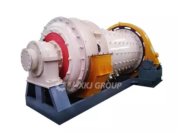
Structure of rod mill
The rod mill adopts a reducer drive mode and central discharge. It mainly consists of the following parts:
Feeding device
The feeding device is a shoe-shaped hopper, and the upper flange is connected with the feeding equipment to receive the fed material. There is an inspection door on the back wall of the hopper, forming a round tube and extending into the spiral barrel mounted on the hollow shaft, through which the material enters the mill.
Rotary part
The rotating part is a cylinder rolled and welded by steel plates. A liner is arranged inside the cylinder, which not only protects the cylinder but also lifts the steel rod to a suitable height to improve the efficiency of sand making. There is an acid and alkali resistant rubber pad between the steel liner and the simplified end cover to reduce noise and vibration.
Large and small gears
The large and small gears are driven by helical gears with balanced work, small impact and long life. It adopts spray lubrication and regular oil injection, which reduces the labor intensity of workers, has a good lubrication effect and reduces the consumption of lubricating oil.
Main bearing
The main bearing supports all the weight of the rotating part, steel bars, materials, etc. The bearing bush is supported on the spherical seat, which can play a self-defense function to adapt to manufacturing and installation errors.
After the long-term work of the main bearing, the bearing bush will wear and tear, resulting in the sinking of the hollow shaft. The sealing bracket can be adjusted downward to ensure that the seals and the hollow shaft are in good contact.
Saturday from 10:00 to 17:00
SINGAPORE 409051
Saturday from 10:00 to 17:00
Sunday is a day off